
Made a waterfall; added aluminum flashing to improve flow.
Using a powerful pump and splitters to even out flow.
Sealant worked well; no leaks

Spencer- Built mechanism for fish feeder; stepper motor works.
Will use wood for final version.
http://www.instructables.com/id/Control-DC-and-stepper-motors-with-L298N-Dual-Moto/?ALLSTEPS


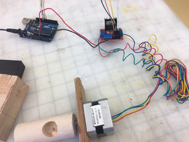
Had to sand shaft due to centering issues.

- DC motor 1 “+” or stepper motor A+--Red
- DC motor 1 “-” or stepper motor A- Green
- 12V jumper – remove this if using a supply voltage greater than 12V DC. This enables power to the onboard 5V regulator
- Connect your motor supply voltage here, maximum of 35V DC. Remove 12V jumper if >12V DC----Red to Vin on Arduino
- GND
- 5V output if 12V jumper in place, ideal for powering your Arduino (etc)
- DC motor 1 enable jumper. Leave this in place when using a stepper motor. Connect to PWM output for DC motor speed control.
- IN1--orange--D8
- IN2--yellow--D9
- IN30--green--D10
- IN4--white--D11
- DC motor 2 enable jumper. Leave this in place when using a stepper motor. Connect to PWM output for DC motor speed control.
- DC motor 2 “+” or stepper motor B+ Yellow
- DC motor 2 “-” or stepper motor B- Blue
The key to successful stepper motor control is identifying the wires – that is which one is which. You will need to determine the A+, A-, B+ and B- wires. With our example motor these are red, green, yellow and blue. Now let’s get the wiring done.
Connect the A+, A-, B+ and B- wires from the stepper motor to the module connections 1, 2, 13 and 14 respectively. Place the jumpers included with the L298N module over the pairs at module points 7 and 12. Then connect the power supply as required to points 4 (positive) and 5 (negative/GND).
Once again if your stepper motor’s power supply is less than 12V, fit the jumper to the module at point 3 which gives you a neat 5V power supply for your Arduino. Next, connect L298N module pins IN1, IN2, IN3 and IN4 to Arduino digital pins D8, D9, D10 and D11 respectively.
Finally, connect Arduino GND to point 5 on the module, and Arduino 5V to point 6 if sourcing 5V from the module. Controlling the stepper motor from your sketches is very simple, thanks to the Stepper Arduino library included with the Arduino IDE as standard.
Question about measuring delays- need real time clock?Jonathan-
Demonstrated cardboard prototypes for small aquaponics system.

Bike Shelter group-
Drew model in SketchUp of bike shelter using square stock:

System would use battery, solar cells, would include skateboard rack.

Lights bring up issue of light pollution.
Could use motion sensor to only turn on lights when needed.
Suggested including bicycles and bike rack in SketchUp model for scale, as for example:


Toby-
showed plastics grinder. Discussed re-purposing an oven to recycle plastics scrap.
No comments:
Post a Comment